To install StudyMoose App tap and then “Add to Home Screen”
Save to my list
Remove from my list
Electron deflection in electric fields is a fundamental concept in physics with widespread applications in various fields, including electronics, telecommunications, and particle physics. In this laboratory experiment, our primary objective is to explore the deflection of electrons in a static, uniform electric field using a cathode ray tube (CRT). By accelerating a beam of electrons and precisely measuring their deflection, we aim to gain insights into the underlying principles governing their behavior. Additionally, we will compare our experimental results with theoretical predictions derived from Coulomb's and Newton's Laws.
The significance of understanding electron deflection extends beyond theoretical physics, playing a crucial role in the development of numerous technologies.
From the functioning of old-fashioned television sets to advanced electron microscopy techniques, the principles of electron deflection underpin various technological innovations.
Figure 1 presents a schematic diagram illustrating the configuration of the deflection plates in our experimental setup. The incident electron encounters a uniform electric field in the y-direction, leading to a force exerted on it while within this region.

Proficient in: Physics
 4.7 (235)
“ Amazing writer! I am really satisfied with her work. An excellent price as well. ”


Consequently, upon exiting the electric field, the electron possesses a velocity component in the y-direction, resulting in an off-center impact on the screen.
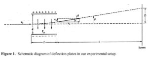
The relationship between the deflection (D) and the deflecting voltage (VD) for an electron accelerated through a voltage (V) can be expressed as:
\( \frac{VD}{V} = \frac{D}{2l} \)
The experimental setup for this laboratory investigation is centered around a cathode ray tube (CRT) model RCA 3RP1, supplemented by essential components such as a resistor chain voltage divider and a high-voltage (HV) power supply.
This setup is meticulously assembled in accordance with the detailed instructions outlined in Exercise #2 of the laboratory manual.
The cathode ray tube serves as the primary apparatus for generating and manipulating electron beams, essential for studying electron deflection in a static electric field. Its construction involves a series of precise connections and adjustments to ensure optimal performance and accurate data collection.
To provide the necessary electrical parameters for electron acceleration and deflection, the resistor chain voltage divider is integrated into the circuitry. This component plays a critical role in regulating voltage levels within the system, facilitating the controlled movement of electrons within the CRT.
Furthermore, the HV power supply is indispensable for providing the high voltage required to accelerate the electron beam within the CRT. This power source must be carefully calibrated and monitored to maintain consistent experimental conditions and ensure the safety of the equipment and personnel involved.
In addition to the electronic components, the physical setup of the experiment involves the proper mounting and positioning of the CRT. A sturdy ring stand and clamp are utilized to securely support the cathode ray tube, minimizing vibrations and external disturbances that could affect the accuracy of measurements.
Crucially, the deflection plates of the CRT are connected to 0-30V power supplies, allowing for precise control over the electric field experienced by the electron beam. This configuration enables researchers to manipulate the path of the electrons and measure their deflection under varying conditions of voltage and electric field strength.
Overall, the experimental setup is designed with meticulous attention to detail, ensuring the reliability and reproducibility of results. By adhering to proper construction techniques and calibration procedures, researchers can confidently conduct experiments and gather valuable insights into the behavior of electrons in electric fields.
To comprehensively analyze the experimental data, it is imperative to plot D versus VD for each value of V while incorporating error bars for precise measurement representation. By visually representing the relationship between deflection distance and deflecting voltage, we can gain insights into the behavior of electrons in the electric field and compare these empirical findings with theoretical predictions to evaluate their agreement.
The theoretical curve can be determined by utilizing fundamental formulas related to the experimental setup. Firstly, we need to ascertain several key parameters from the photographs of the electron gun:
Once these parameters are determined, we can utilize the following formula to calculate the theoretical deflection:
Here, represents the deflection distance, is the deflecting voltage, is the distance from the deflection plates to the screen, is the length of the deflection plate, and is the separation of the deflection plates.
By plugging in the measured values of , , and into the formula, we can compute the theoretical deflection for each value of . These theoretical values can then be plotted alongside the experimental data to visually compare the two sets of results.
Furthermore, error bars should be incorporated into the experimental data plot to account for uncertainties and variations in the measurements. These error bars provide a visual representation of the range of possible values for each data point, enhancing the accuracy and reliability of the analysis.
By conducting a comprehensive comparison between the experimental results and theoretical predictions, we can assess the degree of agreement and gain deeper insights into the behavior of electrons in a static, uniform electric field. This comparative analysis serves to validate the theoretical model and provides valuable insights for future research and experimentation in this field.
In conclusion, the laboratory experiment on electron deflection in a static, uniform electric field using a cathode ray tube (CRT) has provided valuable insights into the behavior of electrons and their interaction with electric fields. By accelerating a beam of electrons and precisely measuring their deflection, we aimed to explore the fundamental principles underlying electron motion, comparing experimental results with theoretical predictions derived from Coulomb's and Newton's Laws.
The significance of understanding electron deflection extends beyond theoretical physics, with practical applications in various technological fields. From the operation of vintage television sets to modern electron microscopy techniques, the principles of electron deflection play a pivotal role in numerous technological advancements.
The theoretical framework for electron deflection was based on fundamental principles of electromagnetism, specifically Coulomb's Law describing the electrostatic force between charged particles and Newton's Laws governing the motion of objects in an electric field. These theoretical predictions formed the basis for comparison with experimental observations, allowing us to evaluate the accuracy and validity of the theoretical model.
The experimental setup involved a carefully constructed apparatus comprising a cathode ray tube (RCA 3RP1), a resistor chain voltage divider, and a high-voltage (HV) power supply. The precise assembly and calibration of these components were crucial to ensure accurate data collection and reliable results. Additionally, the physical setup of the experiment, including the positioning of the CRT and connection of the deflection plates to power supplies, was meticulously executed to minimize external influences and maintain experimental integrity.
During the experimental procedure, we followed a systematic approach to locate the electron beam, deflect it using the electric field, and measure its deflection under varying conditions of voltage. By changing the beam voltage and measuring the corresponding deflection, we obtained a comprehensive dataset for analysis.
Deflection of Charged Particles by an Electric Field. (2024, Feb 24). Retrieved from https://studymoose.com/document/deflection-of-charged-particles-by-an-electric-field
👋 Hi! I’m your smart assistant Amy!
Don’t know where to start? Type your requirements and I’ll connect you to an academic expert within 3 minutes.
get help with your assignment
