To install StudyMoose App tap and then “Add to Home Screen”
Save to my list
Remove from my list
The ability to analysis a circuit gives a potential electrical engineer the ability to learn how to problem solve in a theoretical and practical sense which in turn develops industry skills in which will follow them for life, and allow a solid knowledge base for the rest of their career. This report covers the analysis of a DC circuit in order to determine unknown values within a circuit and covers the design process of a DC circuit when specific voltages are required and current and resistors values are unknown.
Introduction
This laboratory focuses predominately on DC circuit analysis and design although, as a result of this, many fundamental aspects of electrical engineering and circuit theory are brought to light. Without the knowledge of circuit theory and fundamental DC circuit analysis and design there is no hope for an electrical engineer to succeed in their job. The knowledge and understanding of these principles in circuit theory are a necessity in order to develop higher-order knowledge and skills within an occupational and furthering academic environment.
Considering circuit theory is said to be the corner stone of electrical technology and thus the corner stone of electrical engineering, many fundamentals of circuit analysis and design are required to be elaborated upon for the educational purposes of this report.

Proficient in: Physics
 4.7 (346)
“ This writer never make an mistake for me always deliver long before due date. Am telling you man this writer is absolutely the best. ”


To begin, "Energy is a scalar quantity associated with the state (or condition) of one or more objects" [ (Walker, 2011) ] which is an important concept to be aware of for later definitions. "The quantity of electricity is said to be electric charge, charge is also said to be 'conservative' in that it can be neither created nor destroyed" [ (Smith, 1980) ].
Charge is then directly related to current as it is "defined by the electricity transported by one ampere of current in one second" [ (Rizzoni, 2009) ].
Current is thus defined as "the electric charge passing through the area A per unit of time" [ (Smith, 1980) ] which as previously stated relates directly to the definition of charge. From this point, voltage is also but a small step from charge due to its relation, through flow of electric charge. "The energy-transfer capability of a flow of electric charge is determined by the electric potential difference or voltage through which the charge moves" [ (Smith, 1980) ].
Thus from these three consecutive definitions it can already be seen how they are all interrelated and therefore, considering the allow for electric circuits to function, are essential to circuit theory as a base knowledge. It can be considered fairly basic knowledge that a circuit has three basic elements being, current (measured in Ampere's: A), voltage (measured in Volts: V) and resistance (measured in Ohms: ? ). Resistance is yet to be defined and thus a definition is as follows: In many applications, resistance must be inserted into a circuit.
The purpose of this resistance is either to reduce the current or to produce a desired IR voltage drop. The components manufactured with a specific resistance for these uses are called resistors. (Grob, 1977) From these three basic elements of a circuit it was Georg Ohm who constructed the aptly known Ohm's Law used in circuit theory.
Ohms Law is simply: Voltage = Current ? Resistance (V = IR)(V) (1)
From this equation the simplistic variations of DC circuit analysis is effectively born.
Ohm's Law not only allows the basics to be explained in simple terms but also allows for more complex analysis methods such as Node Voltage and Mesh Current analysis to be formed with the assistance of such laws as Kirchhoff's Current Law (KCL) and Kirchhoff's Voltage Law (KVL). KCL is defined as: The algebraic sum of the currents into any point of the circuit must equal the algebraic sum of all the currents out of that point. Otherwise, charge would accumulate at the point, instead of having a conducting path [ (Grob, 1977) ]. KVL is similarly defined as:
For each mesh followed continuously in its tracing direction the algebraic summation of all the instantaneous voltage drops is zero (Pike, 1971). Where a mesh is defined as "a loop that does not contain any other loops" [ (Nilsson, 2011) ] and a loop is defined as "a path whose last node is in the same as the starting node" [ (Nilsson, 2011) ] and a node is defined as a point where two or more circuit elements join" [ (Nilsson, 2011) ]. KVL, KCL and Ohm's Law are all important tools for circuit analysis, especially using the node voltage method.
A worked example for KCL and Ohm's law is included for Figure 1 next; which can also be directly applied to that of KVL in the same manner in place of KCL.
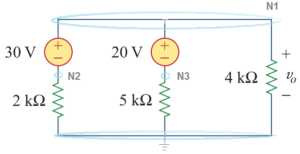
Figure 1: Simple dual voltage source (V1 and V2) circuit, with three resistors (R1, R2 and R3) and four nodes (N1, N2, N3, N4).
From Figure 1, using KCL it can be said that at node two: i1+ i2= i3(A) (2) Which can then be substituted for Ohm's law to give: Va-VbR1+Vc-VbR2= VbR3 (V) (3) When values are then substituted into equation three, the voltage 'b' at node two is equal to 24 volts.
The same can be applied to KVL in nodal voltage analysis, however, instead of the summation of currents into nodes, the summation of voltages are taken and then Ohm's Law used to allow for simultaneous or algebraic solving just as completed above. Therefore, from this example it can be seen that KCL, KVL and Ohm's law are very important in the analysis of electrical circuits, especially in the node voltage method and must be a part of the base knowledge for circuit theory of an electrical engineer. The Lab Exercise
Figure 2 will be referenced significantly throughout this section of the report as it was analysed in terms of node voltages and then used as a design tool in terms of resistance and current when node voltages were known.
Figure 2: Circuit constructed for analysis of 'Va', 'Vb' and 'Vc' then secondly for design purposes concerning resistor and current values when voltages were known. For the initial analysis of Figure 2, the node voltage method was selected and conducted via the use of KCL in conjunction with Ohm's Law. This was conducted on nodes one, two and three, with node four acting as the reference node.
Design of Electronic Circuits Lab Report. (2024, Jan 17). Retrieved from https://studymoose.com/document/design-of-electronic-circuits-lab-report

👋 Hi! I’m your smart assistant Amy!
Don’t know where to start? Type your requirements and I’ll connect you to an academic expert within 3 minutes.
get help with your assignment

